Measurement FundamentalsImportant Terminology for Measurement System Selection
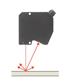
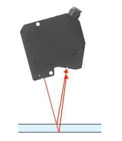
| Mounting conditions / Mounting mode | To measure a target using a laser displacement sensor, the receiver must be able to obtain the light reflected from the object. With measurement systems that use the triangulation method, and depending on the surface conditions of an object, sensor heads are installed at an angle so that reflected light can be received properly.
|
|---|---|
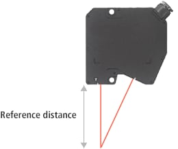
| Reference distance | The reference distance is the sensor heads default zero point. This is commonly represented as the distance from the bottom of the sensor head to the centre of the measuring range.
|
| Measurement range | The measurement range is the range that a sensor can perform measurement. Measurement ranges are generally written as ±xx mm based on the reference distance. [Example] Reference distance: 30 mm Measurement range: ±5 mm A laser displacement sensor as described above can measure targets in the following range.
|
| Light source | In non-contact measurement systems, the transmitter irradiates the target with light, and the reflected light is captured by the receiver. A wide variety of light sources can be used for this illumination, including red semiconductor lasers, blue semiconductor lasers, white light, SLDs, and green LEDs. The type of light source used is determined by the principle of the measurement system. Using the appropriate lens or light receiving element for a light source, makes high-accuracy measurement possible. |
| Spot diameter | With non-contact measurement systems, there are generally two types of beam spots, elliptical and circular. Elliptical spots are used to measure average heights within an area and are less susceptible to influence from the target's surface roughness. However, as the spot size increases, the less suitable it becomes for profiling shapes or measuring small targets. On the other hand, because the size of a circular spot is smaller, it is effective at performing these inspections.
|
| Repeatability | Repeatability represents the overall difference in a measurement value taken at the same location on a target. |
| Linearity |
Linearity is an indicator of a measurement system's capability. The value represents the maximum error value between an ideal value and the actual measurement result. For example, when a target is moved 1 mm using a measurement system with a linearity of ±5 µm, the displayed value is said to possibly include an error margin of ±5 µm (e.g., 9.995 µm to 1.005 µm).
Linearity graph
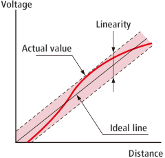
|
| Temperature characteristics | Temperature characteristics represent the maximum measurement error value that occurs when the temperature of the sensor head changes one degree. Inside the sensor head is a lens and a CMOS sensor, and jigs to secure these items. Temperature changes cause these components to expand and contract, changing the position of the imaging location on the CMOS and causing errors. Temperature characteristics are defined as ±○○% of F.S./℃, where F.S. represents the measurement range. Calculation is performed as follows. It is reasonable to say that measurement systems with smaller temperature characteristics are better. For example, with a measurement system that has a temperature characteristic of 0.01% of F.S./℃ and a measurement range of ±3 mm (F.S. = 6 mm), the linearity will be 0.01% × 6 mm = ±0.6 µm. |
| Ambient light | Ambient light refers to the maximum illumination intensity of an external light source at which the measurement system can measure without being affected. |
| Ambient temperature | Ambient temperature refers to the temperature environment at which operation of the measurement system can be guaranteed. |
| Ambient humidity | Ambient humidity refers to the humidity environment at which operation of the measurement system can be guaranteed. |
| Vibration resistance | Vibration resistance is an index that shows how much of an influence vibration will have on a measurement system. The displayed values indicate the evaluation performed. For example, the general description of “10 to 55 Hz, 1.5 mm double amplitude, 2 hours each in X, Y, and Z directions” specifically implies that the following test has been performed. Vibration performed for 2 hours at a frequency of 10 to 55 Hz at an amplitude of ±0.75 mm in the X direction ⇓ Vibration performed for 2 hours at a frequency of 10 to 55 Hz at an amplitude of ±0.75 mm in the Y direction ⇓ Vibration performed for 2 hours at a frequency of 10 to 55 Hz at an amplitude of ±0.75 mm in the Z direction |
| Sampling frequency / Sampling speed | The sampling frequency / sampling speed represents the number of data points the measurement system can measure per second. A measurement system with a sampling frequency of 100 Hz can perform 100 measurements in 1 second. Measurement systems with faster sampling frequencies are capable of providing more accurate target measurements with inline measurement, and because multiple averaging processes can be performed at once, measurements will be stable. |
| Received-light wave pattern | The received-light wave pattern represents the state of light received by the light-receiving element. The vertical axis represents the strength of the light, and horizontal axis shows the position on the light-receiving element. Checking the shape of the received-light wave pattern makes it possible to determine whether the current measurement is being performed accurately.
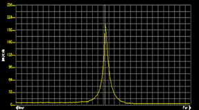
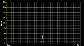
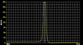
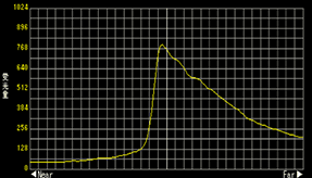
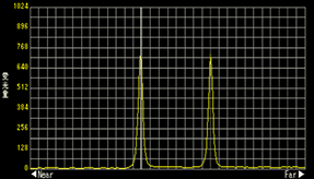
|
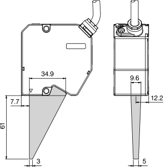
| Optical axis, optical axis region | The central axis of the light emitted from the measurement system's transmitter is called the optical axis. The optical axis region diagram shows the path of light from the transmitter to the receiver. Because no light will reach the target or the receiver if a jig or other object enters this region, measurement will not be possible. Optical axis region diagramx |
| Power supply voltage | The power supply voltage is the necessary voltage required to operate the device. With a specification of 24 VDC ±10%, a DC power supply of 24 V with fluctuations of no more than ±2.4 V is required. |
| Maximum current consumption | The maximum current consumption represents the amount of current that is consumed when operating the device. It is necessary to select a device that has a power supply with a larger capacity than the maximum current consumption. |


