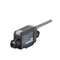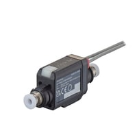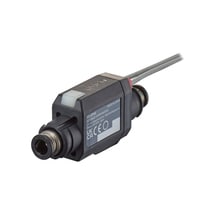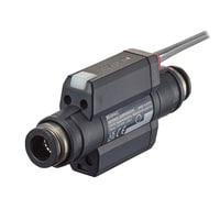
Flow and Pressure Dual Sensor
FD-EP series
Specs Flow and Pressure Dual Sensor FD-EP series
Sensor head
|
Model |
FD-EPH4 |
FD-EPH5 |
FD-EPH6 |
FD-EPH7 |
FD-EPH8 |
|||
|
Image |
|
|
|
|
|
|||
Data Sheet (PDF) |
||||||||
|
Supported pipe diameter |
Pipe outer diameter |
ø4 *1 |
3/16” |
ø6 *1 |
1/4” |
ø8 *1 |
||
|
Applicable outer diameter range |
Polyurethane |
4.0 ±0.1 mm |
4.76 ±0.15 mm |
6.0 ±0.1 mm |
6.35 ±0.15 mm |
8.0 ±0.1 mm |
||
|
Nylon |
4.0 ±0.08 mm |
4.76 ±0.1 mm |
6.0 ±0.08 mm |
6.35 ±0.1 mm |
8.0 ±0.08 mm |
|||
|
Pipe materials |
Plastic piping that can be connected to one-touch couplings |
|||||||
|
Supported fluids |
Air, nitrogen, argon, non-corrosive gases*2 |
|||||||
|
Supported fluid temperatures |
−10 to +60°C |
|||||||
|
Pressure resistance |
1 MPa |
|||||||
|
Flow detection principle |
Transmission time difference method |
|||||||
|
Flow specifications |
Rated flow |
(volumetric flow) |
25 L/min |
30 L/min |
60 L/min |
100 L/min |
||
|
(at 20°C, atmospheric pressure) *Initial display |
Gas at 20°C, 0.0 MPa |
|||||||
|
Gas at 20°C, 0.2 MPa |
75 L/min |
90 L/min |
180 L/min |
300 L/min |
||||
|
Gas at 20°C, 0.4 MPa |
125 L/min |
150 L/min |
300 L/min |
500 L/min |
||||
|
Gas at 20°C, 0.6 MPa |
175 L/min |
210 L/min |
420 L/min |
700 L/min |
||||
|
Measurement accuracy |
±(2.0% of RD+1.0% of F.S.)*3*4 |
|||||||
|
Repeatability |
2.5% of F.S. at 250 ms response time*3*5 |
|||||||
|
Pressure specifications |
Rated pressure |
-100 kPa to +0.75 MPa *However, flow cannot be measured in the -100 to -50 kPa range. |
||||||
|
Overall accuracy |
±2.0% of F.S.*3 |
|||||||
|
Repeatability |
2.5 ms response time: ±0.4% of F.S. |
|||||||
|
Display resolution |
Instantaneous flow |
0.01/0.1 L/min |
||||||
|
Integrated flow |
0.01/0.1/1/10/100 L |
|||||||
|
Pressure |
0.1/1 kPa |
|||||||
|
Environmental resistance |
Enclosure rating |
IP65 (IEC60529) |
||||||
|
Ambient temperature |
-10 to +60°C (no freezing) |
|||||||
|
Relative humidity |
35 to 85% RH (no condensation) |
|||||||
|
Vibration resistance |
10 to 500 Hz; Power spectral density: 0.816 G2/Hz; X, Y and Z directions |
|||||||
|
Shock resistance |
100 m/s2, 16 ms pulses, 1000 times each for X, Y, and Z directions |
|||||||
|
Material |
Sensor body (part not in contact with fluids) |
PBT/PAR/Iron/Brass electroless nickel plating/POM/NBR/Stainless steel/Aluminium |
PBT/PAR/Iron/Brass electroless nickel plating/POM/NBR/Stainless steel |
PBT/PAR/Iron/Brass electroless nickel plating/POM/NBR/Stainless steel/Aluminium |
PBT/PAR/Iron/Brass electroless nickel plating/POM/NBR/Stainless steel |
PBT/PAR/Iron/Brass electroless nickel plating/POM/NBR/Stainless steel/Aluminium |
||
|
Flow path (part in contact with fluids) |
PBT/Brass electroless nickel plating/NBR/Nylon |
|||||||
|
Weight |
Approx. 127 g |
Approx. 128 g |
Approx. 127 g |
Approx. 129 g |
Approx. 145 g |
|||
|
*1 For stable detection, a pipe inner diameter equal to or greater than the inner diameter of this product is recommended. |
||||||||
|
Model |
FD-EPH9 |
FD-EPH10 |
FD-EPH12 |
FD-EPH13 |
|||
|
Image |
|
|
|
|
|||
Data Sheet (PDF) |
|||||||
|
Supported pipe diameter |
Pipe outer diameter |
3/8” |
ø10 *1 |
ø12 *1 |
1/2” |
||
|
Applicable outer diameter range |
Polyurethane |
9.53 ±0.15 mm |
10.0 ±0.15 mm |
12.0 ±0.15 mm |
12.7 ±0.15 mm |
||
|
Nylon |
9.53 ±0.1 mm |
10.0 ±0.08 mm |
12.0 ±0.1 mm |
12.7 ±0.1 mm |
|||
|
Pipe materials |
Plastic piping that can be connected to one-touch couplings |
||||||
|
Supported fluids |
Air, nitrogen, argon, non-corrosive gases*2 |
||||||
|
Supported fluid temperatures |
−10 to +60°C |
||||||
|
Pressure resistance |
1 MPa |
||||||
|
Flow detection principle |
Transmission time difference method |
||||||
|
Flow specifications |
Rated flow |
(volumetric flow) |
150 L/min |
250 L/min |
|||
|
(at 20°C, atmospheric pressure) *Initial display |
Gas at 20°C, 0.0 MPa |
||||||
|
Gas at 20°C, 0.2 MPa |
450 L/min |
750 L/min |
|||||
|
Gas at 20°C, 0.4 MPa |
750 L/min |
1250 L/min |
|||||
|
Gas at 20°C, 0.6 MPa |
1050 L/min |
1750 L/min |
|||||
|
Measurement accuracy |
±(2.0% of RD+1.0% of F.S.)*3*4 |
||||||
|
Repeatability |
2.5% of F.S. at 250 ms response time*3*5 |
||||||
|
Pressure specifications |
Rated pressure |
-100 kPa to +0.75 MPa *However, flow cannot be measured in the -100 to -30 kPa range. |
|||||
|
Overall accuracy |
±2.0% of F.S.*3 |
||||||
|
Repeatability |
2.5 ms response time: ±0.4% of F.S. |
||||||
|
Display resolution |
Instantaneous flow |
0.1/1 L/min |
|||||
|
Integrated flow |
0.1/1/10/100/1000 L |
||||||
|
Pressure |
0.1/1 kPa |
||||||
|
Environmental resistance |
Enclosure rating |
IP65 (IEC60529) |
|||||
|
Ambient temperature |
-10 to +60°C (no freezing) |
||||||
|
Relative humidity |
35 to 85% RH (no condensation) |
||||||
|
Vibration resistance |
10 to 500 Hz; Power spectral density: 0.816 G2/Hz; X, Y and Z directions |
||||||
|
Shock resistance |
100 m/s2, 16 ms pulses, 1000 times each for X, Y, and Z directions |
||||||
|
Material |
Sensor body (part not in contact with fluids) |
PBT/PAR/Iron/Brass electroless nickel plating/POM/NBR/Stainless steel |
PBT/PAR/Iron/Brass electroless nickel plating/POM/NBR/Stainless steel/Aluminium |
PBT/PAR/Iron/Brass electroless nickel plating/POM/NBR/Stainless steel |
|||
|
Flow path (part in contact with fluids) |
PBT/Brass electroless nickel plating/NBR/Nylon |
||||||
|
Weight |
Approx. 193 g |
Approx. 180 g |
Approx. 201 g |
Approx. 208 g |
|||
|
*1 For stable detection, a pipe inner diameter equal to or greater than the inner diameter of this product is recommended. |
|||||||
Amplifier Units
|
Model |
FD-EPA1 |
FD-EPA1C |
FD-EPA0 |
|||
|
Image |
|
|
|
|||
Data Sheet (PDF) |
||||||
|
Type |
Cable Type |
M12 connector type*5 |
Zero Line Type*6 |
|||
|
No. of control outputs |
3 |
─*7 |
||||
|
No. of analog outputs |
1 |
─ |
||||
|
No. of external inputs |
2 |
─*7 |
||||
|
Power supply cable |
2 m, strand wire, 8-core |
100-mm pigtail, M12 terminal, 8-pin |
No cable |
|||
|
Response time (90% response) |
Flow |
50 ms/100 ms/250 ms/1 s/5 s (selectable, default 250 ms) *1 |
||||
|
Pressure |
2.5 ms/10 ms/50 ms/100 ms/250 ms/1 s/5 s (selectable, default 2.5 ms) *1 |
|||||
|
Input/output |
Control output 1, 2, 3 |
Instantaneous flow/integrated flow/pressure/alert output/predictive maintenance output/seating (output 1 only)/pulse output NPN/PNP |
||||
|
Analog output |
Instantaneous flow/pressure 4–20 mA/0–20 mA (switchable), load resistance 260 Ω or less |
|||||
|
External inputs 1, 2 |
Zero flow/flow origin adjustment/atmospheric pressure correction/pressure zero shift/accumulation reset/application learning/application reset |
|||||
|
Network compatibility |
IO-Link*2 |
NU Series |
||||
|
No. of expansion units |
─ |
8 units for one NU parent unit, 4 units for one |
||||
|
Protection circuit |
Protection against reverse power connection, output overcurrent, output surges, |
Protection against head cable miswiring |
||||
|
Power supply |
Power voltage |
24 VDC +20%/−10% (including ripple), Class2/LPS |
24 VDC ±10% (including ripple), Class2/LPS |
|||
|
Power consumption |
1870 mW (excluding load current)*3*4 |
1400 mW (excluding load current)*4 |
||||
|
Environmental resistance |
Ambient temperature |
-10 to +55°C (no freezing) *4 |
||||
|
Relative humidity |
35–85% RH (no condensation) |
|||||
|
Vibration resistance |
10 to 500 Hz; Power spectral density: 0.816 G2/Hz; X, Y and Z directions |
|||||
|
Shock resistance |
100 m/s2, 16 ms pulses, 1000 times each for X, Y, and Z directions |
|||||
|
Material |
Main unit: Polycarbonate, FG terminals: copper/iron |
|||||
|
Weight |
Approx. 90 g |
Approx. 42 g |
Approx. 26 g |
|||
|
*1 Analogue output response time is 5 ms additional and 63% response. |
||||||


